It is noteworthy that the recently launched Llama 3.1 model boasts an impressive parameter scale of 405 billion.
As intelligent computing centres expand, the optical market is increasingly occupying a significant share of data centres. During the 100G era, the ratio of optical modules to networks was approximately 1:1; however, in the 400G era, this ratio has shifted to 7:3, underscoring the critical importance of optical modules within clusters. This article will focus on the failure rates of optical modules, analyze the primary causes of failure in traditional Digital Signal Processing (DSP) modules, compare failure rates utilizing LPO technology, and discuss the advantages presented by LPO modules.
The current status of optical modules in computing power networks
The diagram presented illustrates the current mainstream network architecture utilized in the RoCE Ethernet solution for intelligent computing centres. In this configuration, servers connect to the computing power network via a 400G high-speed network card. Additionally, a data centre switch equipped with a 51.2T switching chip establishes a three-tier architecture capable of supporting a cluster scale exceeding ten thousand cards.
The requirement for the module rate at the Intelligent Computing Centre has reached 400G, with considerations for implementing 800G interconnection in the switch interconnections. Currently, the predominant switching chip available is the 51.2T model, which utilizes 112G SerDes technology, necessitating the adoption of Q112 packaging for the corresponding optical modules on the switch side. On the network card side, the OSFP packaging format is primarily utilized, allowing for the selection of models based on the required distance during deployment.
The operational principles of Digital Signal Processing (DSP) optical module
Optical Module Failure Rate Index
● Definition of Efficiency Indicators
The failure rate associated with an optical module is the aggregation of the failure rates of all its constituent components. For example, if a specific optical module has a theoretical failure rate of 155.63 FIT, it suggests that one could expect 155.63 failures to occur within one billion hours of operation.
The duration required for a single module to fail once can be calculated as one billion divided by 155.63, yielding approximately 8647744 hours. This translates to an estimated failure occurrence of one module within 8647744 hours. While this data may suggest a high level of reliability for the module, a comprehensive evaluation of the statistics across the entire cluster is warranted.
|
GPU Credit card scale (piece)
|
4096
|
8192
|
16384
|
32768
|
|
Number of optical modules required for the cluster (blocks)
|
16384
|
32768
|
98304
|
196608
|
|
The interval time (in hours) between one failure in all optical modules
|
528
|
Two hundred sixty-four
|
88
|
44
|
As illustrated in the accompanying figure, we present the number of optical modules required at various cluster scales, along with the interval time during which all-optical modules are expected to experience a failure for the first time. It is evident that this relationship exhibits a monotonically decreasing trend as the number of modules increases.
In a cluster scale exceeding ten thousand cards, the failure rate of a single module is exacerbated. For instance, within a cluster of 32,000 cards, module failures may occur approximately every two days; thus, from this perspective, the module failure rate merits significant consideration.
There are two principal factors that influence variations in the failure rate of optical modules: the number of components within the module and the operational temperature of the module itself.
The relationships governing these changes are as follows:
Analysis of the failure rates associated with traditional Digital Signal Processing (DSP) optical modules reveals several shortcomings:
From the analysis above, it is clear that the primary causes for the failure of DSP modules are the substantial number of devices involved and the high operating temperatures, including those associated with DSP and peripheral chips, as well as EML and VCSEL lasers. To effectively mitigate the failure rate of these modules, it is essential to address the root causes. In the subsequent sections, we will introduce the Linear Drive Pluggable Optics (LPO) module solution.
LPO Optical Module Solution
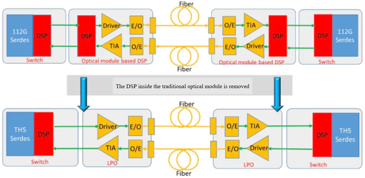
The LPO module eliminates the traditional DSP chip found in conventional DSP modules, utilizing the DSP integrated within the switching chip to process electrical signals. This module employs standard performance driver and TIA chips, carefully selecting an appropriate electro-optical conversion strategy to achieve superior transmission performance. The electro-optical conversion component may incorporate VCSEL, EML, or silicon optical technologies, with silicon optical exhibiting enhanced linearity and reduced electrical reflection. To ensure a reliable supply and increased performance, Ruijie Network has implemented silicon optical technology solutions. For further insights into the foundational concepts of LPO, readers may refer to prior articles detailing the advent of LPO technology as an innovative tool for network construction in intelligent computing centres.
● LPO Analysis of Module Failure Rate
|
LPO + silicon photonics
|
DSP + Silicon Photonics
|
DSP+EML
|
DSP+VCSEL
|
|
1
|
1.31
|
1.64
|
2.35
|
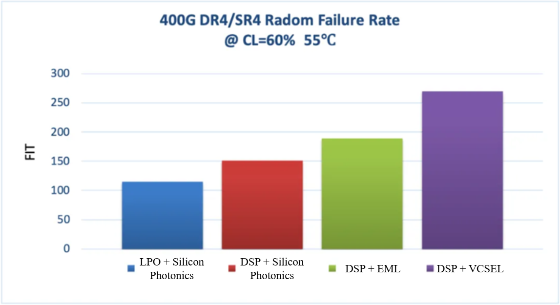
The accompanying chart illustrates the failure rate ratios of various technical solutions for 400G modules at a standardized operating temperature of 55°C. It is evident that, at this consistent operating temperature, the failure rate associated with the LPO combined with silicon photonics solution is the lowest. In comparison, the failure rates of the other solutions range from 1.31 to 2.34 times greater than that of the LPO and silicon photonics configuration.
This comparative analysis is fundamentally employed to evaluate the failure rates of different modules while ensuring a constant operating temperature. However, it is important to note that, in actual deployment scenarios, the operating temperature of LPO and silicon optical modules is typically lower than that of the DSP solution, thus contributing to a further reduction in the failure rate.
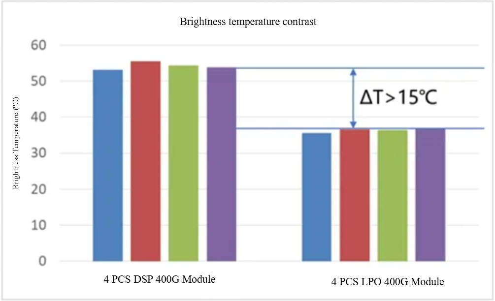
As illustrated in the above figure, when considering the same ambient temperature, the operating temperature of the LPO module is approximately 15°C lower than that of the DSP module.
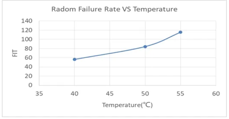
When the temperature of the LPO module is reduced from 55°C to 40°C, the failure rate is observed to decrease by 50%, thereby indicating enhanced reliability, as demonstrated in the subsequent figure.
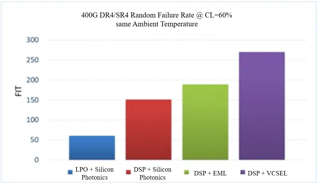
In the context of real-world deployment scenarios, a comparison of 400G modules utilizing different technical solutions at identical ambient temperatures reveals that the failure rate of the LPO and silicon photonics solution is further diminished, a benefit attributable to the lower operating temperature of the module.
Summary

Performance Parameters of LPO Optical Modules
The mere presence of a lower module failure rate does not suffice for the LPO optical module to entirely supplant the DSP module. It is imperative to also assess the usability of the optical module, with particular emphasis on Bit Error Rate (BER) and Sensitivity (SEN). The performance metrics of these two indicators must align with the established protocol threshold standards.
● Evaluation Methods for Optical Module BER and SEN
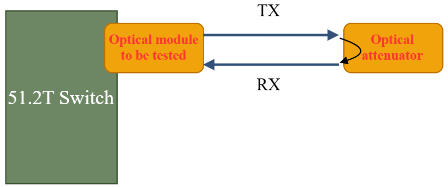
Through the adjustment of optical attenuation, it is possible to ascertain the BER at various receiver optical power levels. The aggregation of all test results allows for the generation of a BER versus optical power curve. As the optical power is systematically diminished, resulting in a leftward shift of the horizontal axis on the chart, a point is reached where the BER matches the Forward Error Correction (FEC) threshold specified at 2.4e-4. The optical power recorded at this juncture is designated as the sensitivity (SEN) of the optical module. The typical BER is evaluated in scenarios where optical attenuators are not employed, ensuring results remain within the BER error floor range.
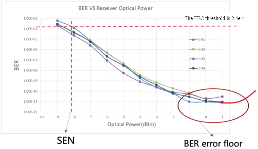
The SEN optical module's capacity to withstand lower optical power levels is particularly advantageous for practical deployments, addressing issues such as diminished optical power due to dirty connectors, reduced launching optical power, or high insertion loss associated with fibre optic connectors.
● Performance Parameters of the LPO DR Module
The following presents test data for various module schemes under room temperature conditions in short fibre scenarios.

From the BER data chart, the following observations can be made:
1. The BER of the LPO DR Module exceeds the protocol threshold, demonstrating a margin of five orders of magnitude.
2. The BER parameters of the LPO DR and DSP combined with silicon photonics solutions are comparable, and both exhibit superiority over the DSP combined with EML solution by two to three orders of magnitude.
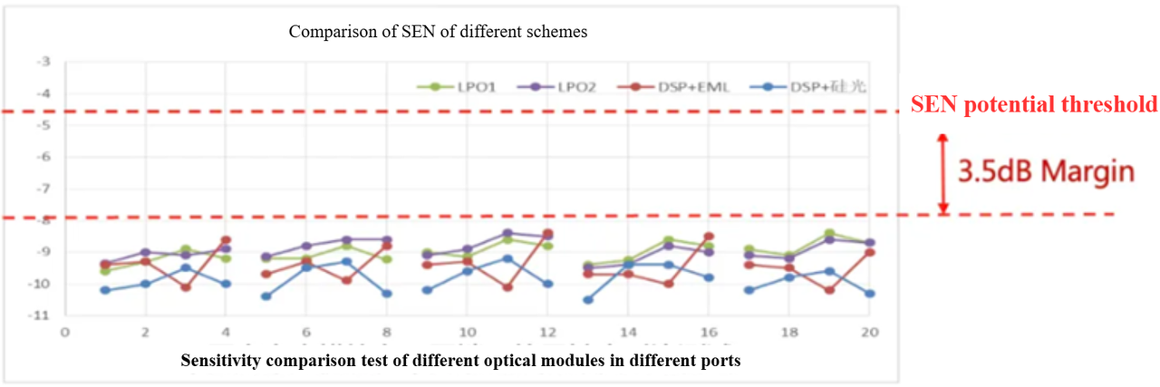
From the SEN data chart, the following can be observed:
1. The SEN of the LPO DR Module shows a margin of approximately 3.5 dB relative to the protocol threshold.
2. The SEN parameters across the three solutions exhibit minimal variance.
In summary, the analysis indicates that the optical performance parameters of LPO combined with silicon photonics are closely aligned, while the combination of DSP with silicon photonics outperforms the DSP coupled with EML plan. Therefore, it is plausible to conclude that the LPO module can effectively replace the existing DSP DR plan.
Additional Benefits of LPO Optical Modules
Beyond attributes of high reliability and availability, LPO optical modules present additional value in various dimensions:
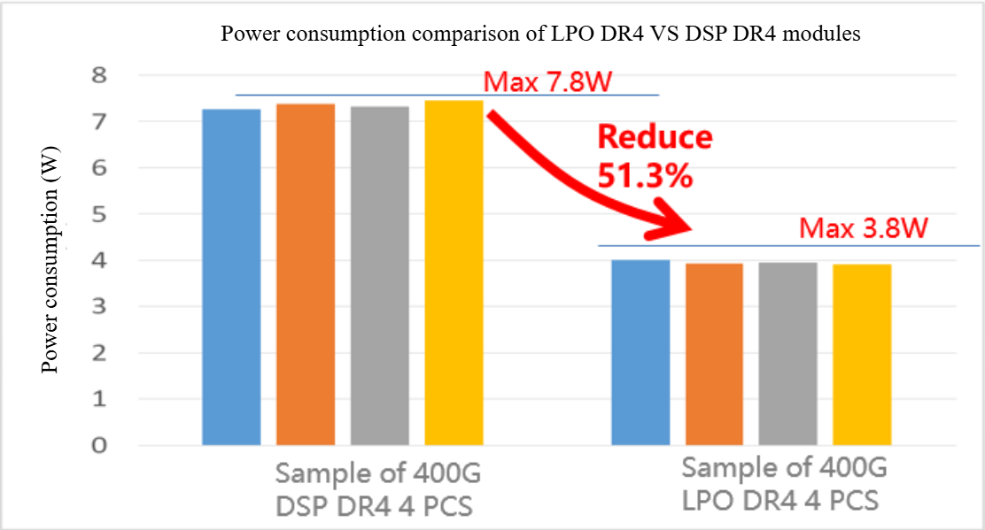
1. Lower Power Consumption: By eliminating the DSP chip, the maximum power consumption of the optical module can be reduced by approximately 51.3%, achieving a value below 4W (with case temperature assessed at 70°C).
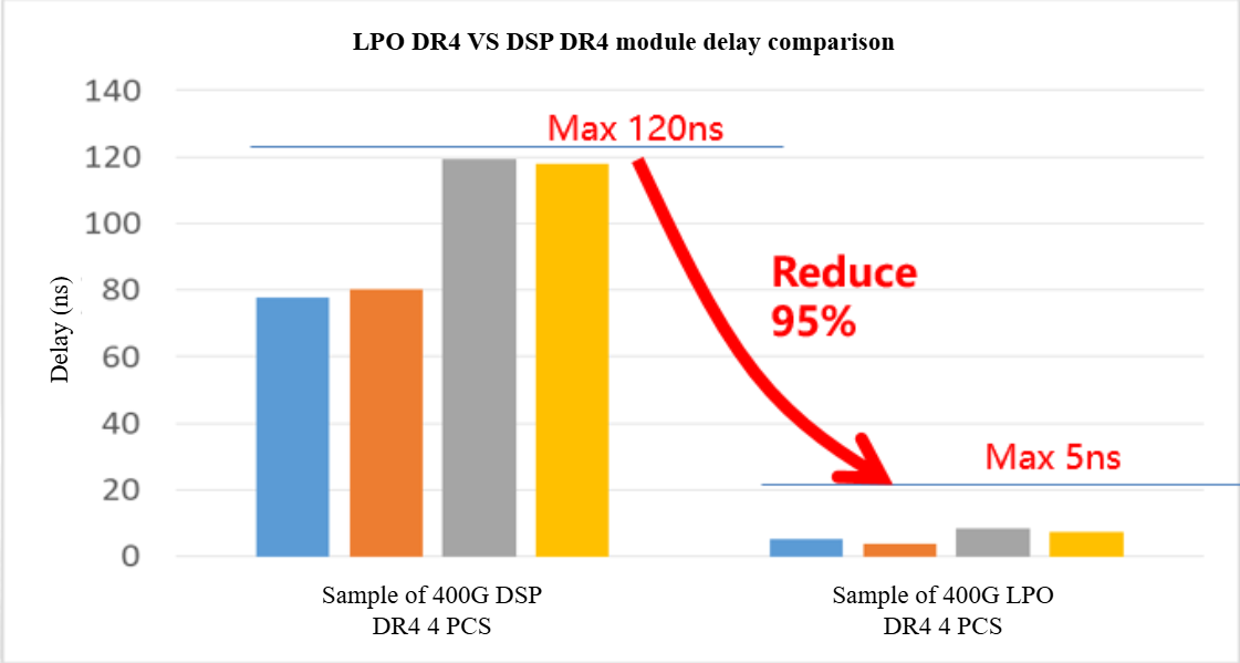
2. Reduced Latency: The omission of the DSP chip from the module minimizes one processing step, resulting in a latency reduction of 95%, thus satisfying the requirements of low-latency application scenarios.
3. Enhanced Supply Chain Stability: Traditional DSP modules face challenges related to the limited availability of DSP chips and VCSEL lasers, which are currently in short supply and have extended delivery timelines, presenting risks for large-scale deployments. The LPO module's design negates the necessity for a DSP chip, instead employing silicon photonics technology. This strategy effectively mitigates supply risks associated with critical components by circumventing reliance on tightly-supplied DSP chips and VCSEL components.
Ruijie LPO Optical Module Products

|
Index
|
400G Q112 DR4 LD
|
800G OSFP DR8 LD
|
800G OSFP 2DR4 LD
|
|
Transmission distance
|
500mSingle-mode fibre
|
500mSingle-mode fibre
|
500mSingle-mode optical fibre
|
|
Initiating optical power
|
0 to 4 decibel-mill watts
|
0~4dBm
|
0~4dBm
|
|
Full temperature BER Floor
|
<1e-8
|
<1e-8
|
<1e-8
|
|
Sensitivity OMA
|
<-7dBm
|
<-7dBm
|
<-7dBm
|
|
Power consumption
|
Max 4W
|
Max 8W
|
Max 8W
|
|
Delay
|
<5ns
|
<5ns
|
<5ns
|
|
Case Temperature
|
0~70°C
|
0~70°C
|
0~70℃
|
|
Optical port type
|
MPO12/APC
|
MPO16/APC
|
2xMPO12/APC
|
Ruijie Networks is dedicated to advancing AIGC computing power network scenario planning and has developed three proprietary optical modules for LPO DR to address the interconnection requirements of three distinct network architectures.
Currently, the company is engaged in collaborative adaptation testing with leading manufacturers; further updates will be provided. OFC 2024|Ruijie Networks partners with ByteDance to demonstrate the capabilities of the 800G LPO optical module.
As a comprehensive service expert in the GenAI era, Ruijie Networks is committed to delivering full-stack products and solutions that encompass Infrastructure as a Service (IaaS) to Platform as a Service (PaaS). Our offerings include high-performance networks and optimized GPU computing power scheduling, with the objective of significantly enhancing production efficiency and reducing operational costs through innovative technological solutions. We firmly believe that through our endeavours, we can foster a more intelligent, efficient, and reliable future for our clients. We invite collaboration as we explore opportunities within the AI era together.
Related Blogs:
Exploration of Data Center Automated Operation and Maintenance Technology: Zero Configuration of Switches
Technology Feast | How to De-Stack Data Center Network Architecture
Technology Feast | A Brief Discussion on 100G Optical Modules in Data Centers
Research on the Application of Equal Cost Multi-Path (ECMP) Technology in Data Center Networks
Technology Feast | How to build a lossless network for RDMA
Technology Feast | Distributed VXLAN Implementation Solution Based on EVPN
Exploration of Data Center Automated Operation and Maintenance Technology: NETCONF
Technical Feast | A Brief Analysis of MMU Waterline Settings in RDMA Network
Technology Feast | Internet Data Center Network 25G Network Architecture Design
Technology Feast | The "Giant Sword" of Data Center Network Operation and Maintenance
Technology Feast: Routing Protocol Selection for Large Data Centre Networks
Technology Feast | BGP Routing Protocol Planning for Large Data Centres
Technology Feast | Talk about the next generation 25G/100G data centre network
Technology Feast | Ruijie Data Center Switch ACL Service TCAM Resource Evaluation Guide
Silicon Photonics Illuminates the Path to Sustainable Development for Data Centre Networks
How CXL Technology Solves Memory Problems in Data Centres (Part 1)
CXL 3.0: Solving New Memory Problems in Data Centres (Part 2)
Ruijie RALB Technology: Revolutionizing Data Center Network Congestion with Advanced Load Balancing
Multi-Tenant Isolation Technology in AIGC Networks—Data Security and Performance Stability
Multi-dimensional Comparison and Analysis of AIGC Network Card Dual Uplink Technical Architecture
Featured blogs
- CXL 3.0: Solving New Memory Problems in Data Centres (Part 2)
- Ruijie RALB Technology: Revolutionizing Data Center Network Congestion with Advanced Load Balancing
- Multi-Tenant Isolation Technology in AIGC Networks—Data Security and Performance Stability
- Multi-dimensional Comparison and Analysis of AIGC Network Card Dual Uplink Technical Architecture
- A Brief Discussion on the Technical Advantages of the LPO Module in the AIGC Computing Power Network


